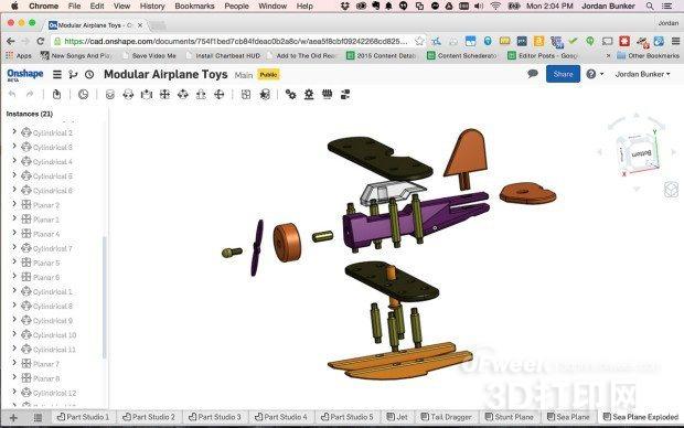
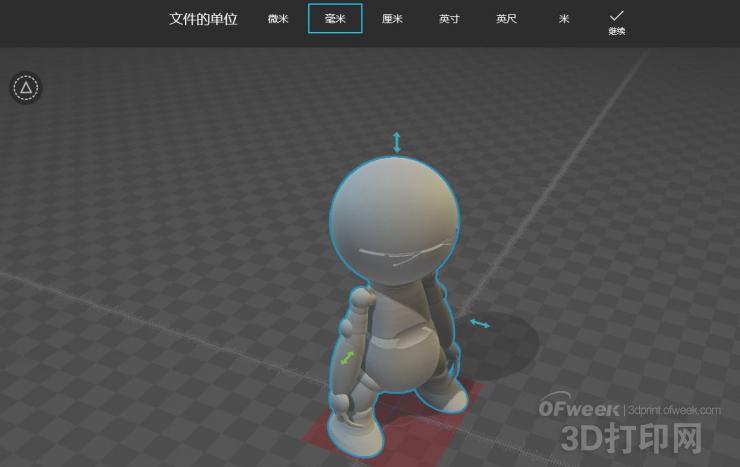
The rise of 3D printing technology and the maker movement has always been complementary. This technology allows makers to quickly create their own designs at ever-lower cost. More and more enthusiasts are therefore from machinery. The field is moving into the software arena. So where do we start to understand 3D printing ? First, let's take a look at the software technologies and tooling terms that 3D printing needs. Some of these technologies and tools have already been widely used in CNC machine tools. (3DP refers to 3D printing, while CNC index control machine) CAD (3DP / CNC) CAD, or Computer-aided design, is a computer software tool that can be used to create 2D or 3D design models. Before CAD entered the field of 3D printing, it has in fact been widely used in the construction and manufacturing fields. OnShape CAD software working interface CAM (CNC) CAM refers to Computer-aided manufacturing, which is a production method that can be used on CNC milling machines and cutting machines to generate tool working paths (using G codes) by means of computer software. It uses a common 2D file format that allows the user to determine which parts need to be ground or cut, the speed of the work, and so on. G code (3DP / CNC) The G code instructions are used directly to guide the operation of the CAM system. In modern design software, G code is completely generated by software, and people basically no longer write G code directly. Specific G codes can be used to control the speed, direction, depth, rotation, and other switches and sensors of the tool. G code transmitter (3DP / CNC) Once the G code is generated, the Transmitter software will transfer these instructions to the machine (usually via USB). Although there are individual G code sender software that uses an open source toolchain, most commercial software is now integrated with a G code sender. Grid Editor (3DP / CNC) Once the designed 3D model is converted to the STL format, the resulting triangle layout is often referred to as a "grid." The Grid Editor allows the user to directly edit the points on the grid: directly control the design shell of the 3D model by dragging, stretching, shrinking, and panning. OpenSCAD (3DP) The software can be used to generate 3D shapes, assemble parts into complex systems, and even directly parameterize designs. Compared to traditional CAD programs, OpenSCAD does not require drawing - all designs are defined by the program, and then the compiler converts the relevant design into the corresponding model. Slicer (3DP) The 3d printer is accumulated by laminar lamination. The work of the slicer software (Slicer) is to divide the designed 3D printing model into single layers of single printing (the thickness of the single layer is determined by the printing precision). The G code of the control path, speed, and print temperature output by the slicer software. Both the closed source and open source slicer software are available on the market. STL (3DP / CNC) This is the most common format for 3D printing, and files in this format are also common in CNC machine tool "2.5D" milling. The STL format file describes the surface of the model through a series of triangles to construct a 3D object. It is also worth mentioning that the model of the STL file has no unit (one of which can represent 1 mm or 1 cm), so it is important to know how the file is generated. Cling Film Food Wrap,Cling Film,Kitchen Cling Film,Pvc Packaging Film DONGGUAN YEE HUP TRADING CO,.LTD , https://www.yeehupack.com


Great science: 3D printing technology design terminology highlights